Defect analysis of steel drum mold flanging and coiling process
Yang Wenliang
In recent years, with the continuous improvement of the automation degree of steel drum production equipment in China, the barrel making process has been developing towards a simpler and more scientific direction. The original steel drum rolling flange (rolling tube) process has been gradually replaced by the mold flanging (rolling tube) process, which not only improves the production efficiency, but also greatly improves the quality of the flanging (coil). However, with the advancement of processes and equipment, new process defects have arisen, and some of the quality defects often found in steel drum mold flanging (coiled) are also special problems caused by this new process.
As far as the current situation is reflected by various enterprises, the quality problems frequently encountered in the process of steel drum mold flanging (rolling tube) mainly include burring, coiled tube not in place, barrel deformation, uneven width of burring, excessive burring In other cases, especially the deformation of the barrel body is the most common problem, which has become the main defect of the mold flange (coiled tube), and it is difficult for many enterprises to solve. Figure 1 shows the physical diagram of the deformation of the barrel in the common mold flanging (rolling tube) process.
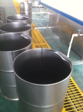
Figure 1 Deformation of the barrel
Below, we will analyze and analyze the influencing factors affecting the process defects of the barrel flange (rolling tube).
First, the impact of the size of the barrel body
It is assumed that the design and manufacture of the equipment and the mold itself are correct. In this case, the size of the barrel blank directly affects the deformation of the barrel when the flange is turned, and whether the size of the flange is qualified.
1, the impact of the diameter of the barrel
The diameter of the barrel is determined by the size of the barrel. Generally speaking, the length of the barrel is determined by the length of the barrel. In the process of using mold flanging or coiling, the length deviation of the barrel of the 200 liter open steel drum should not exceed ±0.5 mm, and the length of the closed steel barrel should not exceed ±1 mm, the diagonal length The error is no more than 1 mm.
When the diameter of the barrel body is too large, there is a relatively large gap between the inner side of the barrel portion and the outer side of the mold positioning core during the flanging process. Due to the stretching force of the barrel body being expanded outward in the diameter direction when the flange is turned, the contact surface between the barrel and the outer edge of the mold is the fulcrum of the force, and the two are in close contact to effectively withstand the reaction force. However, when the diameter of the barrel body is too large, the gap between the contact faces is large. When the flange is turned, the barrel body is bent inward in the diameter direction under the action of the reaction force, and there is no gap between the mold and the barrel body. This bending is blocked by the mold and cannot be achieved. However, when the gap between the mold and the barrel is large, the mold cannot block the bending deformation, and the barrel body is recessed in the vicinity of the barrel. Therefore, in most cases, it is found that the problem that the barrel body is recessed inward near the flange of the barrel is caused by the large size of the barrel body. Figure 2 shows the force applied when the mold is flanged.
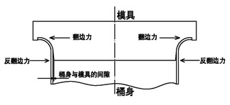
Figure 2 The force of the barrel when the mold is flanged
2, the impact of the height of the barrel body
There are many ways to position the height of the barrel of the barrel mold burring device. Commonly, there are pressure positioning and height positioning. The pressure positioning is generally positioned by the width of the flange of the mold. When the width of the flange reaches the process standard, the edge of the barrel and the groove of the diameter of the flange of the mold are blocked, as shown in Fig. 2, because the height of the barrel has been reached. At the dead point, the feed pressure of the flanging edge rises instantaneously, and the pressure relay of the hydraulic system of the equipment acts, so that the equipment is no longer squeezed, and the mold exits to complete the flanging action. The pressure positioning control method does not require a high error in the blank height of the barrel body, so the barrel body deformation error is generally not generated when the barrel body height error is small.
There is also a high-position method, that is, the distance when the die at both ends of the device is squeezed is adjusted to a fixed value, that is, the position at which the die extrusion is completed according to a certain barrel height. Thus, when the height of the barrel is too small, the width of the flange may not reach the width required by the process standard; and when the height of the barrel is too large, the width of the flange has reached the process standard, but the mold is also in accordance with the initial schedule. The height of the mold is pushed in. Since the limit of the flange width of the mold has been extinguished, the mold continues to be squeezed, and the barrel body will be deformed due to too much axial pressure.
3, barrel body diagonal size is out of tolerance
Under normal circumstances, when the diagonal size of the barrel material is out of tolerance, the weld seam may have a lap joint defect. Sometimes the width of one end is narrow, and the hem of the hem portion may be misaligned. This situation often occurs on old semi-automatic seam welders, and for fully automatic seam welders, it is unlikely.
If there is a misalignment of the edge, the edges of the two ends of the barrel are not on the same plane, or the edge plane is not perpendicular to the axis of the barrel. This may cause a defect in the width of the flange of the barrel, that is, in the week of the barrel In some places, the width of the flange is large, and the process requirements are met. However, in some places, the width of the flange is small and the process size is not met.
Second, the impact of the structure and size of the flanged die
The structure and size of the flanging die have a great influence on the quality of the flanking of the barrel. Some of the forming parts of the flanging die are unreasonable in shape or size design. Some are manufacturing errors of the flanging machine, and some are equipment design defects. More problems are turned over. The long-term grinding loss of the side mold is seriously deformed due to the deformation of the mold forming part. All of the above are common problems that cause quality defects in the flanging process.
In general, as long as the size and shape of the flange can be stabilized to a desired state, the design of the forming portion of the flanged mold is reasonable. However, in many cases, the size and shape of the flanging cannot meet the ideal process requirements, which often causes problems such as excessive flanging or oversize. As shown in Figure 3, the ideal size and shape of the common flanging process for a 200-liter steel drum can be achieved by flanging, and the flanging does not affect the quality of the bead of the steel drum (the dimensions are for reference only).
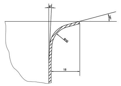
Figure 3 Steel drum flanging process size
1. Structure and size of the forming part of the flanging die
The structure and dimensional design of the flanging die is very important, and many of the flanging process problems are caused by the design structure and size of the flanging die. At present, there are many different styles of design and size of the flanging die at home and abroad. As shown in Figure 4, it is the most representative flanging die structure. This is also the experience of many practices, which is the most used structural type. The structure and dimensions of Figure 4 are effective in ensuring that the flanging process requirements required for Figure 3 are produced (the dimensions in the figures are for reference only).
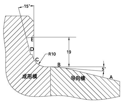
Figure 4 Schematic diagram of the structure and dimensions of the steel drum flanging die
The flange mold shown in Fig. 4 is composed of a forming die portion and a guide die portion. The guiding die facilitates the rapid and accurate entry of the steel drum into the forming die for flanging forming. The surface of the guiding die is composed of A section and B section. The A section has a large inclination and is the barrel leading section, which is responsible for guiding the barrel into the forming mold. The B section has a small inclination and is a positioning section, which is responsible for accurately introducing the two sides of the barrel into the forming section. The mold, and a certain pre-expansion force to the barrel body, can achieve precise positioning, and prevent the gap between the barrel body and the mold to cause deformation of the barrel body (as shown in Figure 2).
In Figure 4, the arc of section C is the forming section of the barrel body, and the edge of the barrel is turned outward by the pressure of the mold through the transition of the arc. Section D is the most important part. In the past, the D section of the flanging die of many enterprises was a straight section connected with the transition of the C section. It is easy to have excessive flanging defects in production. Figure 5 shows. In order to solve the problem of over-flange, most enterprises now adopt advanced experience at home and abroad, and design the D-segment as the trough shape as shown in Figure 4. When the bucket is in the Flange, the edge will enter the D-segment and the free state will appear. That is, at this stage, the edge of the bucket is not subject to any constraint in the opposite direction, thus eliminating the problem of excessive overturning.

Figure 5 Schematic diagram of excessive overturning of the barrel
The E segment in Fig. 4 is the limit phase, that is, when the flange edge reaches the E segment, the flange width process requirement is reached, the flange is stopped, and the flange width is limited to exceed the process requirement width.
2. Structure and size of the forming part of the open barrel barrel
The design of the structure and size of the barrel-rolling tube mold, if unreasonable, may cause defects such as excessive coiling, insufficient coiling, and rounding of the coil. Figure 6 shows a schematic diagram of common coiled tubing defects.
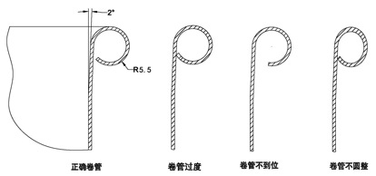
Figure 6 Schematic diagram of common defects in the barrel coil
The normal coiled tube gap is generally about 1 to 2 mm. When the coiled tubing is excessive, the coiled tubing gap is small, or the end of the coiled tubing is tightly coupled to the outer wall of the tub. In this case, there are certain process problems in the production of steel drums. For example, when the steel pulverizing tube is put into the cleaning phosphating process, it is easy to store water or cleaning liquid in the coiled tube, which is difficult to clean.
When the coiled tube is not in place, the gap between the coiled tubes is relatively large, generally more than 3mm. This situation not only affects the appearance of the coiled tubing, but also reduces the strength of the coiled tubing. It may also occur when the barrel mouth is assembled with the lid and the barrel clamp. problem.
When the coiled tubing is not rounded, the coiled tubing may have an elliptical shape, or other irregular circular shape. It is still important to affect the beauty of the barrel mouth. This situation seriously affects the assembly quality of the barrel mouth and the lid and the barrel hoop. Common problems such as poor sealing, easy to drop the lid, or difficulty in assembling the hoop.
In practice, the reasonable structure and dimensions of the barrel-rolled tube die are summarized in Figure 7 (the dimensions in the figure are for reference only).
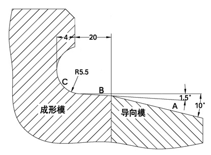
Figure 7 barrel mouth coil mold structure size
The take-up mold shown in Fig. 7 is composed of a forming die portion and a guide die portion. The guiding die facilitates the rapid and accurate entry of the steel drum into the forming die for roll forming. The surface of the guiding die is composed of A section and B section. The A section has a large inclination and is the barrel leading section, which is responsible for guiding the barrel into the forming mold. The B section has a small inclination and is a positioning section, which is responsible for accurately introducing the two sides of the barrel into the forming section. The mold, and a certain pre-expansion force to the barrel body, can achieve precise positioning, and prevent the gap between the barrel body and the mold to cause deformation of the barrel body (as shown in Figure 2).
In Figure 7, the arc of section C is the forming section of the barrel coil, and the edge of the barrel is rolled outward by the pressure of the mold through the transition of the arc. The size and length of the C-arc arc determine the size and shape of the barrel coil. When the arc R is too large, the coiled tube is not likely to be in place; when the R is too small, the overwinding of the coil is likely to occur; when the length of the arc is too large or too small, it is easy to handle the rounding of the coil.
Third, the impact of equipment accuracy
The accuracy of the flanged (coiled) equipment of the barrel has a great influence on the quality of the flanging (rolling tube). Common problems include the concentricity of the flanges at both ends of the barrel and the degree of parallelism. Figure 8 is a schematic diagram showing the coaxiality error of the two ends of the device. Figure 9 is a schematic diagram showing the parallelism of the parallelism of the two ends of the device.
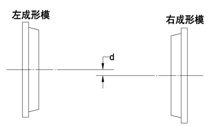
Figure 8 Schematic diagram of the coaxiality error of the flanged die
As shown in Fig. 8, when the axes of the flanging dies at both ends are not on the same straight line, although the planes of the dies at both ends are parallel, there is an error d in the axis. In general, in the case of a 200 liter steel drum, the error d exceeds 3 mm, which causes a large quality impact on the burring process. If the width of the flange is not uniform, the shape of the turn does not meet the requirements of the process, and the flange is cracked, most of them are caused by this situation.
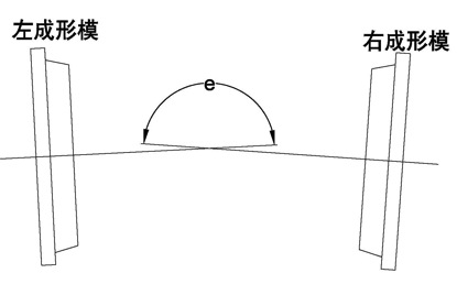
Figure 9 Schematic diagram of the parallelism error of the flanging die
As shown in Fig. 9, when the planes of the flanging dies at both ends are not parallel, the axis also has a certain angle e. In this case, the barrel flanging will have different widths, inconsistent shapes, uneven height of the barrel after the flanging, flange cracking, etc., and problems such as barrel depression. When the angle e is normal, it should be 180°. For a 200-liter steel drum, when the angle error of e exceeds 2°, the quality of the flange of the barrel cannot be guaranteed.
At present, in terms of the actual situation of the national barrel-making equipment, the use of the flanging machine produced by the equipment manufacturer with higher domestic technical level generally does not have the problem of over-conformity of the coaxiality and parallelism of the mold. However, some companies choose equipment manufacturers with poor technical level or equipment designed and manufactured by themselves. The accuracy of this equipment is often not guaranteed.
Fourth, the impact of the quality of the barrel steel material
Sometimes in production, we often find that when the equipment is normal, there will be good and bad conditions in the quality of the flanging process. Sometimes the width of the flanging is too large, sometimes it is too small, sometimes it will be cracked, sometimes it will be rolled. Not in place, etc. In this case, we can test the raw material steel plate or by changing the raw materials of different manufacturers, often find the problem of the material.
There are several common problems in raw materials that affect the quality of the barrel flanging and coiling process:
1. The barrel steel plate has high hardness and rigidity.
2, steel carbon content is too high
3, the thickness of the barrel steel plate is uneven
When the barrel steel plate has high hardness, high rigidity and large carbon content, it often occurs that the flange is not in place, the flange is cracked, and the like. When the thickness of the steel plate of the barrel is too poor, the flanging (coiled tube) may not be in place, and the deformation of the barrel may be deformed.
The situation affected by raw materials is usually complicated. The regular barrel-making enterprises will inspect the raw materials of each batch of incoming materials, and all the indicators can meet the requirements before they can be put into use. However, some companies do not have the test conditions or do not carefully test, often put unqualified materials into production. In this way, the quality of the steel drum is difficult to be guaranteed, and the quality of the process is often inevitable.
This paper mainly analyzes the quality problems of the flanging (rolling tube) process from the aspects of equipment and raw materials. In actual production, when quality problems occur, it is generally necessary to analyze from five aspects: “human, machine, material, law, and ring†to find out where the problem is. If there is a problem in any link, the quality will be unqualified.
Compared with silver mirrors, copper-free mirrors are of a higher grade. After the Silver Mirror is plated with silver, a layer of copper will be plated to protect it to prevent the mirror from being damaged and easily scratched. The copper-free mirror is to replace the copper protective film with a passivation protective film, making the mirror more environmentally friendly and durable. The passivation protective film of the copper-free mirror makes the mirror more wear-resistant, and is superior to ordinary silver mirrors in adhesion and corrosion resistance.
In addition, we also sell Silver Mirror glass, silver mirror commonly known as waterproof mirror, mercury mirror, silver-plated mirror on glass surface, glass mirror, mirror glass, etc. Silver mirrors are widely used in furniture, handicrafts, decoration, bathroom mirrors, cosmetic mirrors, optical mirrors, and car rearview mirrors.

copper free mirror, copper tinted mirror, tinted copper free mirror and glass
Dongguan Huahui Glass Manufacturing Co.,Ltd , https://www.antiquemirrorsupplier.com